
How to Hardwire a Dash Cam with the Charger Plus Hardwire Kit
What is a Dash Cam Hardwire Kit?
There are several ways to install a dash cam. Hardwiring your dash cam is a method of connecting your dash cam to your vehicle’s electrical system with the help of a hardwire kit. The hardwiring kit is a set of wires and accessories designed for connecting a dash cam to a vehicle’s electrical system. This allows the dash cam to be powered directly from the vehicle’s battery, rather than from the cigarette lighter socket or USB outlet.
A hardwiring kit typically includes a fuse, fuse holder, and a wire harness to connect it to the dash cam’s power input. It typically includes a set of instructions on how to install and use the kit, as well as how to determine which fuse is best for the particular vehicle. Dash cam hardwiring kits are typically sold separately from the dash cam itself, although some dash cam manufacturers may offer a combined package. The advantage of hardwiring a dash cam is that it eliminates the need for frequent battery charging or replacement, as well as the potential for power disruption when the vehicle’s engine is shut off. Hardwiring is the safest way to use the parking mode feature on your dash cam.
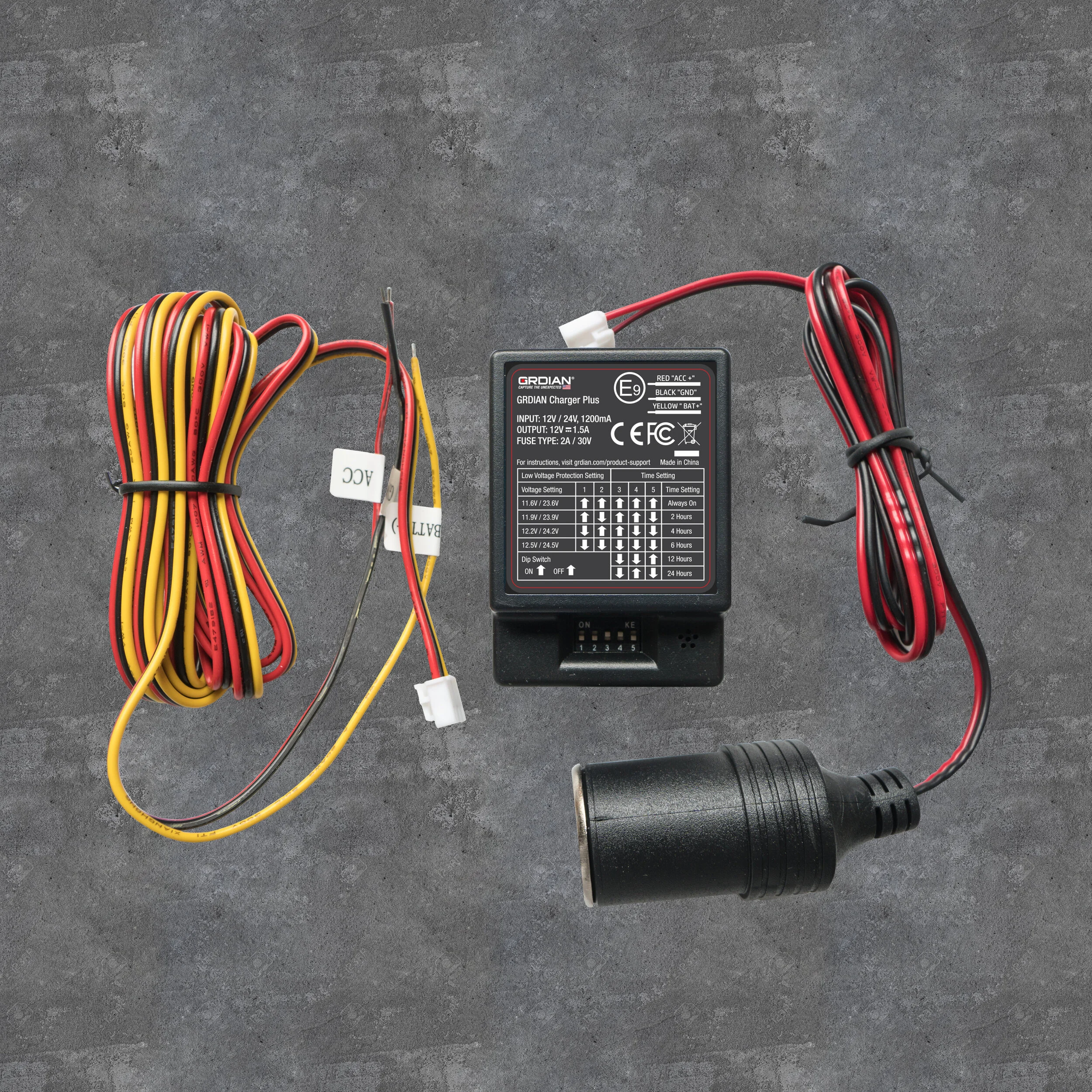
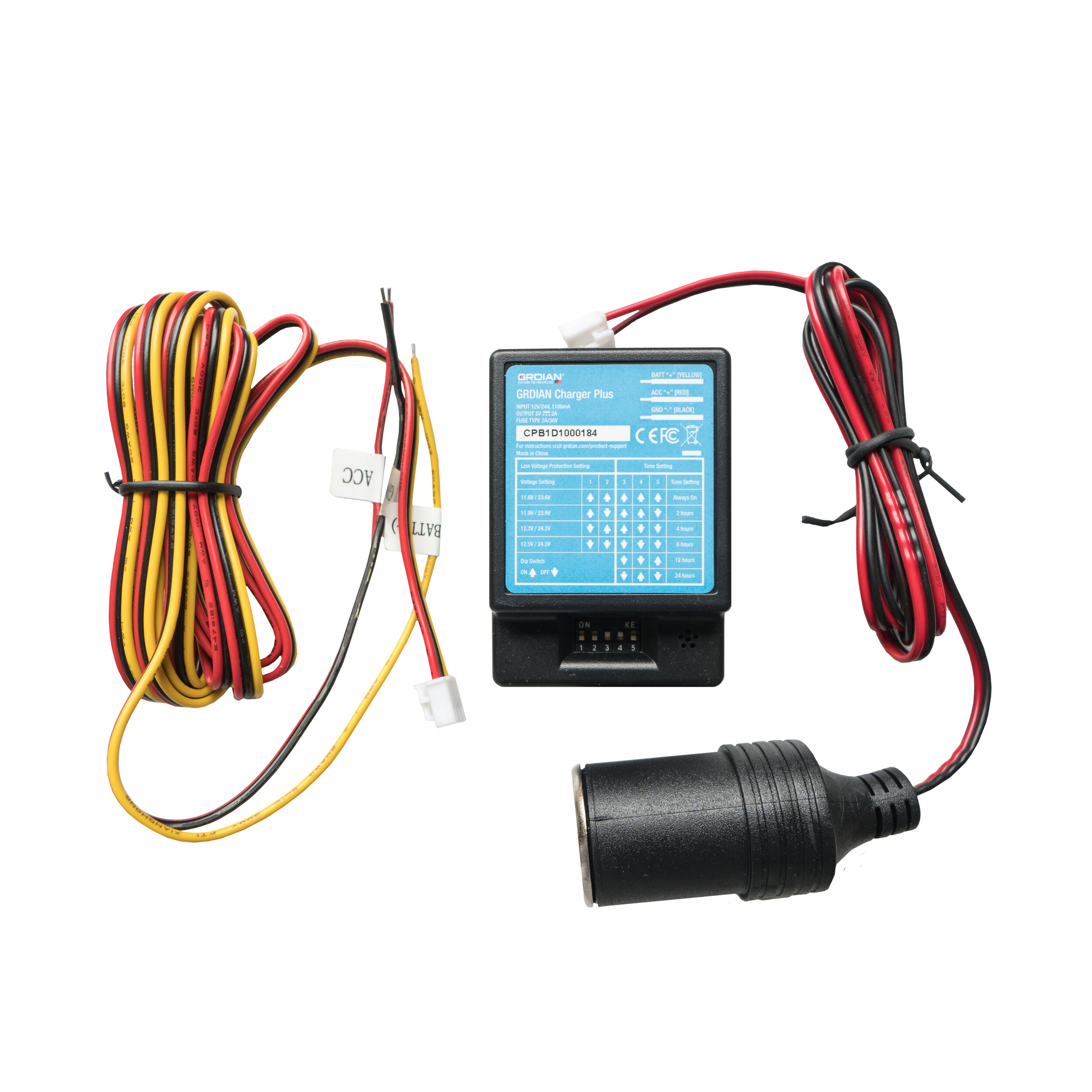
What is the Charger Plus Hardwire Kit?
The Charger Plus Hardwire Kit is a battery discharge prevention device designed to provide a safe method of supplying continuous power to your dash cam even when your vehicle is turned off. By monitoring your vehicle’s battery condition, the Charger Plus Hardwire Kit automatically shuts off your dash cam when the hardwire kit detects a voltage drop below a custom set threshold. In addition to automatic voltage protection, the Charger Plus Hardwire Kit features a built-in countdown timer for automated run-times of 2, 4, 6, 12, 24 hours or always on.
Preparing To Hardwire Your Dash Cam
Before we begin hardwiring your dash cam, we’ll need some tools that will help with the installation process.
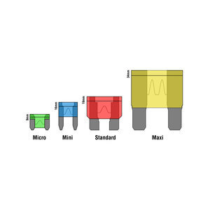
(x2) Add-a-Fuse - Add-a-fuse is used to connect the input connections to a fuse slot in your fuse box.
(x2) 3 Amp Fuse - The 3 amp fuse will be added to your add-a-fuse and will create a new circuit for your dash cam.
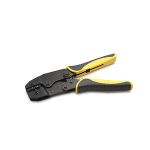
Crimping Tool - A crimp tool will be used to connect add-a-fuses to the input connections.
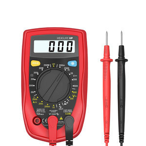
Multimeter - A multimeter will be used to test fuses and your car’s battery.
Pliers - Pliers are used to remove fuses from your fuse box.
WARNING: Improper installation and handling may cause serious damage to your vehicle. GRDIAN is not liable for any mishandling and damages resulting from this guide. Install at your own discretion. Consult your car technician if you continue to have issues. GRDIAN cannot provide help, instructions or recommendations beyond this guide. Please follow each step accordingly to ensure a safe installation.


Step 1: Locate Your Vehicle’s Fuse Box And Battery
Locating your Fuse Box: The location of the fuse box will vary depending on the make, model, and year of your vehicle. Refer to your vehicle’s user manual or fuse box diagram to locate the fuse box for your car. If you are unable to locate a user manual or fuse box diagram contact your manufacturer for more information. A quick search online can quickly yield results as well.
TIP: In most vehicles, the fuse box can be easily found under the dashboard on either the driver or passenger side, under the hood, or in the trunk. If your vehicle has multiple fuse boxes, choose one that is easily accessible and closest to your dash cam.
Locating Your Car Battery: The location of your car battery will differ from car to car. In most cases, your vehicle’s battery can be located inside the engine bay or inside your trunk. Refer to your user manual for the exact location of your battery. If the user manual does not provide this information, simply contact the original car manufacturer or search for answers online.
Step 2: Test Your Car Battery
Once we’ve identified the location of your fuse box and battery, we’ll need to test your battery’s health. A healthy car battery will not only ensure that your vehicle is running properly but will also ensure that your hardwire kit and dash cam will perform as intended.
How to Test Your Car Battery With a Multimeter
Using a multimeter will help determine the overall health of your battery. Your battery should have a negative (-) and a positive (+) terminal, which we will be using to test. If you are unable to reach the terminals, you may need to remove the battery cover to access these terminals.
Plug your black and red lead into your multimeter and set it to 20 DCV.
Use the black lead to touch the negative (-) terminal of your battery and use the red lead to touch the positive (+) terminal of your battery.
Make note of the reading. A healthy battery should read 12.6V or 24.6V. If your battery reads below 11.6V or 23.6V, it may indicate poor battery health. This may cause power-related issues to occur with your dash cam and hardwire kit.
TIP: To get an accurate reading of your battery, we recommend letting your vehicle sit idle for at least 1 hour so that you can get a “resting voltage”.
Step 3: Locate a Ground Point
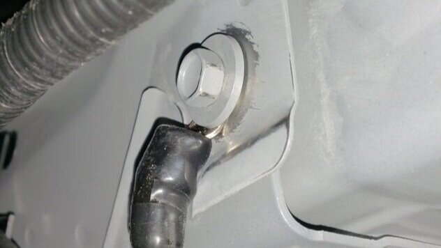
The term “ground” refers to a common return path for an electrical current. The purpose of a ground is to provide a path back to the source of the electrical current in the event of a fault. Grounding your wire is crucial to the safety of yourself and your vehicle in the event of a short circuit. If improperly installed, your hardwire kit may not work.
In most cases, parts of your car’s chassis offer a good ground point. However, vehicles today are built with a combination of metals, spot welds, glued-together uni-body panels and isolated chassis components. Therefore, we cannot assume that a good ground point will automatically be on the chassis. So how do we identify and locate a proper ground point?
Identifying a Ground Point: Continuity Test vs Resistance Test
There are 2 methods to test for proper ground:
The first method is called the continuity test, which measures the flow between 2 points. If the multimeter detects low resistance, the two points are connected electrically and a tone will emit to identify a complete path.
The second method is called the resistance test. This test measures the amount of resistance between 2 points. If there is very low resistance (less than a few Ωs), the two points are connected electrically. The lower the resistance, the better ground it is.
Continuity Test
Using your multimeter, and with the black and red lead plugged in, set your multimeter to Continuity test or 200 ohms.
Using the black lead, touch the negative (-) terminal of your vehicle’s battery and the place the red lead onto your ground point. You should hear a "beep” tone if it is a complete path. If your multimeter does not emit a tone, look for another ground point to test.
Resistance Test
Using your multimeter, and with the black and red lead plugged in, set your multimeter to Resistance Mode or Diode Check.
Using the black lead, touch the negative (-) terminal of your vehicle’s battery and then place the red lead onto your ground point. A good ground point should read less than 0.2 ohms.
Step 4: Locate Constant And Switched Fuses
Constant and Switched fuses are 2 types of electrical circuits. By determining which fuses in your fuse box are constant and switched, we will be able to “piggyback” off of the 2 types of electrical circuits and use them to connect to the Charger Plus Hardwire Kit.
What is a Constant Fuse? Constant or “always hot” fuses receive power regardless if the car is turned on or off. For example, the interior light of your vehicle might use a constant fuse because it provides constant power even when your vehicle is turned off.
What is a Switched Fuse? Switched fuses are the opposite and only receive power when your car is turned on. For example, your moonroof may require you to turn on the car to use.
NOTE: Some vehicles may maintain power for a few minutes after being turned off. We recommend opening your doors and trunk and letting your car sit for ~30 minutes to ensure that your vehicle is completely turned off. Upon returning, avoid opening/closing any doors or trunks that might trigger a switched fuse.
How to Test for a Constant Fuse
Using your multimeter, set the multimeter to 20 DCV. Make sure your vehicle is completely turned off. You may need to let your vehicle sit for a couple of minutes to fully shutdown.
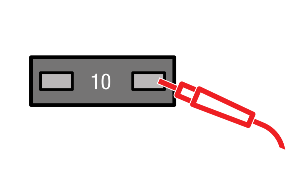
Refer to your fuse box diagram to choose a fuse to test. (Avoid using fuses over 10A and fuses relative to car safety such as brake lights, ECU, cooling fan, etc.)
Place the black lead on your ground point and place the red lead on each end of the fuse. If your multimeter reads 12V, it is a constant fuse. If not, it is a switched fuse.
How to Test for a Switched Fuse
Using your multimeter, set the multimeter to 20 DCV. Make sure your vehicle is completely turned off. You may need to let your vehicle sit for a couple of minutes to fully shutdown.
Refer to your fuse box diagram to choose a fuse to test. (Avoid using fuses over 10A and fuses relative to car safety such as brake lights, ECU, cooling fan, etc.)
Place the black lead on your ground point.
Place the black lead on your ground point and place the red lead on each end of the fuse. If your multimeter reads 0V, it is a switched fuse.
Step 5: Determining Line And Load
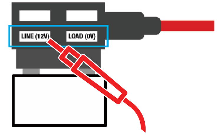
The terms "line" and "load" are shorthand words that refer to the wires that deliver power from the source to a device (line), vs. those that carry power onward to other devices further along the circuit (load). By determining both line and load side, your hardwire kit and dash cam will be properly protected in the event of a overcurrent.
Once we’ve determined a constant and switched fuse, we’ll have to test both sides of each fuse (constant and switched) with a multimeter. The multimeter will tell us which side of the fuse is line and which side is load. This will help us insert the add-a-fuse in the right orientation. As illustrated, the left side of an add-a-fuse is the line, while the right side of an add-a-fuse is the load side.
How to Determine Line and Load Side
Set your multimeter to 20 DCV.
Choose one of your fuses to test (either constant or switched). We’ll repeat the same steps for the other fuse.
Remove your fuse and insert your add-a-fuse into the empty slot.
With the black lead touching your ground point, test for line side by placing the red lead on the bottom left slot of your add-a-fuse. It should read 12V.
Test for load side by placing the red lead on the bottom right slot of your add-a-fuse. It should read 0V.
If the above is true, your add-a-fuse is placed in the correct orientation. If not, remove the add-a-fuse and insert in the opposite direction. Once inserted, repeat steps 4-5 to test.
Repeat the above steps 3-5 for the other fuse.
NOTE: Remember to do this for both your constant and switched fuse.
Step 6: How to Use Add-a-Fuse
Add-a-fuse or add-a-circuit “piggybacks” off of an existing fused circuit so that new electrical components can be added or used. By using a add-a-fuse, we’ll be able to easily add another fused circuit to protect a newly connected device/electrical component. In this case, a dash cam.

Remove either one of the add-a-fuse from Step 5 while remembering the correct orientation of the placement.
Insert the original fuse removed from your car’s fuse box at the bottom of your add a fuse.
Insert the new fuse for your dash cam at the top of the add-a-fuse. (The new fuse must be a lower amperage than the original fuse. For instance, if the fuse you removed from your car is 10A, insert a fuse lower than 10A at the top of your add-a-fuse.)
Repeat the steps 1-4 for the other add-a-fuse.
Step 7: Assembling Add-a-Fuse to the Charger Plus
Now that we have determined a constant and switched fuse, line and load sides, and inserted the correct fuse into your add-a-fuse, we can now connect them all to the hardwire kit.
BATT+ (Yellow) Line: Attach your constant add-a-fuse to the hardwire kit’s BATT+ (Yellow) wire. Use a crimp tool to attach.
ACC+ (Red line) Line: Attach your switched add-a-fuse to the hardwire kit’s ACC+ (Red) wire. Use a crimp tool to attach.
GND (Black) Line: Attach the ground wire to the ground point by tightening the screw to the wire.
Step 8: Connecting Component Wires to the Hardwire Kit
Once we’ve established a proper ground, constant and switched fuses, line and load side, we’ll be able to put everything together.
Insert both of your add-a-fuses back into their corresponding slot while making sure it is in the correct orientation as determined in Step 4 and 5.
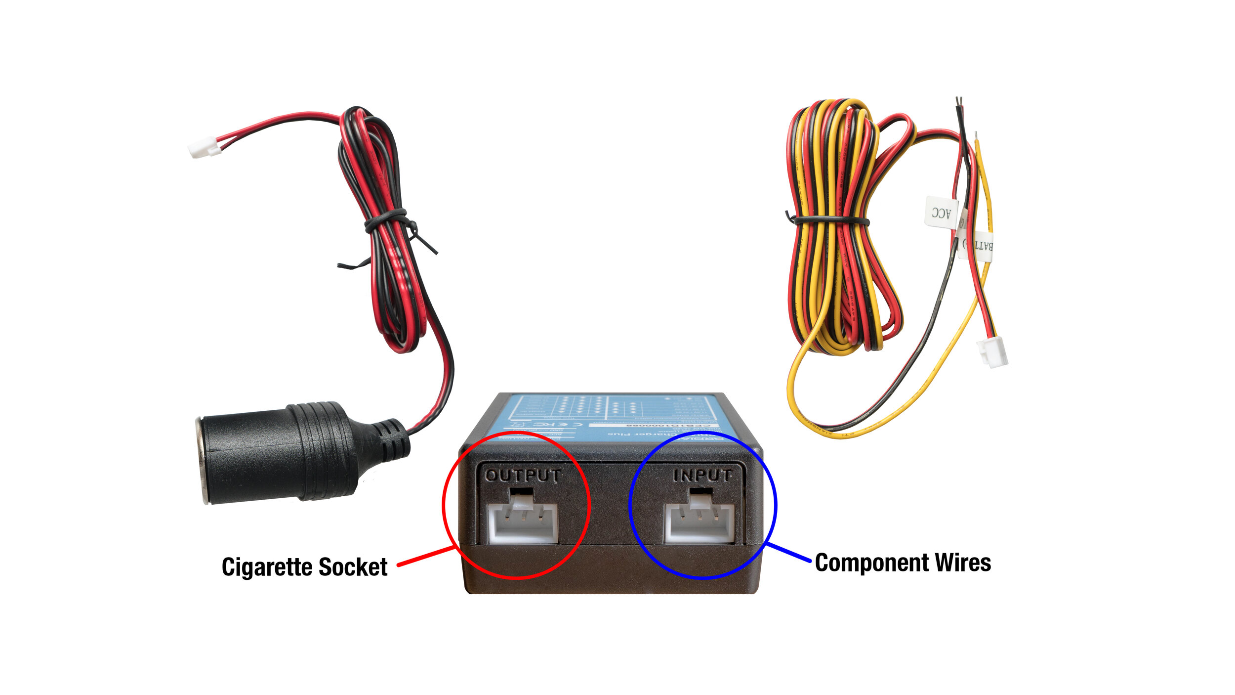
Connect the Cigarette Socket to the OUTPUT terminal of the Charger Plus.
Connect the Component Wires to the INPUT terminal of the Charger Plus.
Insert a USB car charger into the Cigarette Socket. Plug your dash cam’s USB power cable into the car charger and connect it to your dash cam.
Once everything is connected, turn ON your vehicle. You will notice either a RED or GREEN light indicator on the Charger Plus module.
If the GREEN light is ON, you have successfully installed your hardwire kit. If there is a RED light instead, turn off your vehicle and wait for a couple of minutes to ensure your vehicle is completely turned off. Turn your vehicle back on. If you installed the hardwire kit correctly, the indicator light should now turn green.
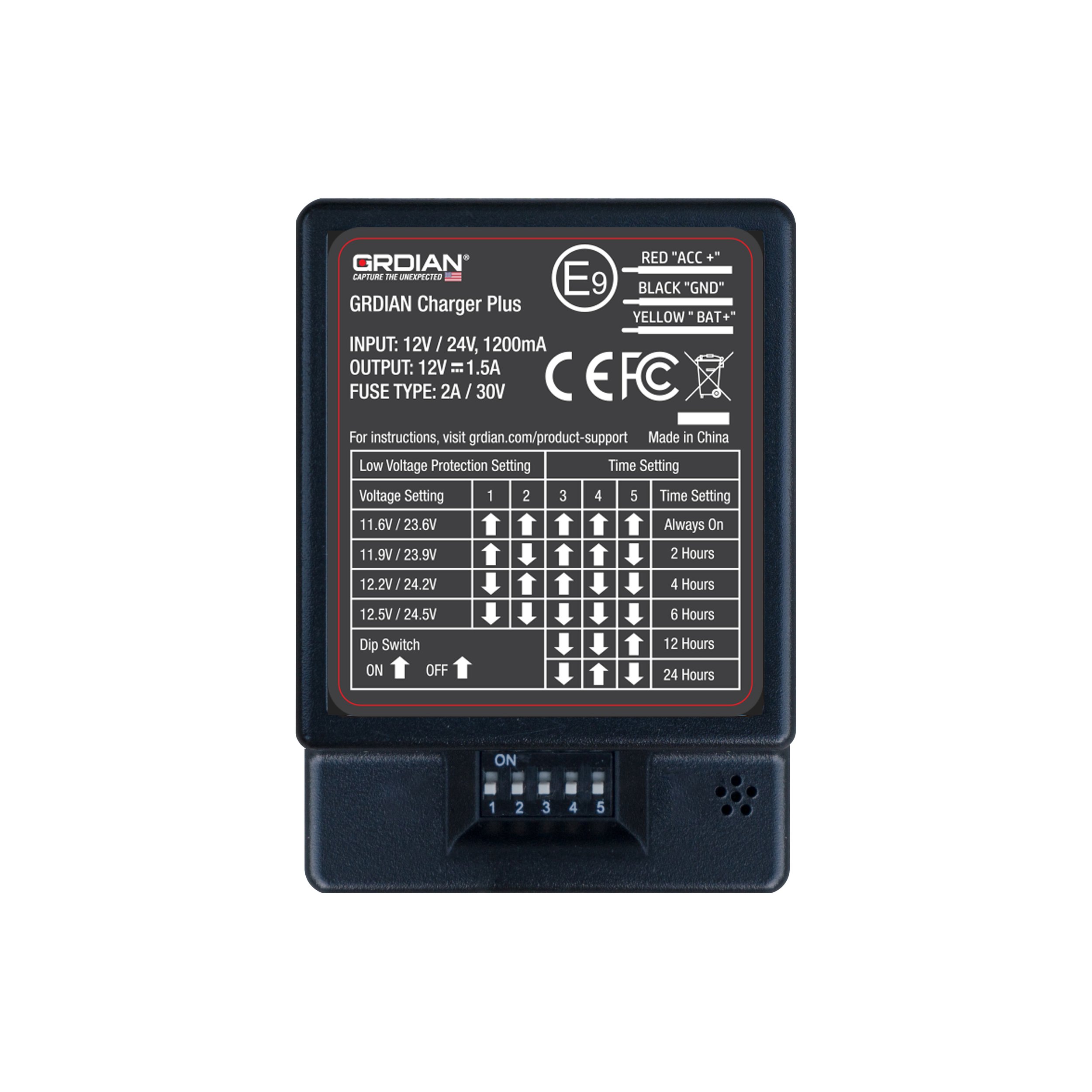
Configuring the Charger Plus Hardwire Kit
The Charger Plus features custom voltage protection settings against battery drainage and a built-in countdown timer.
To configure the voltage setting and countdown timer setting, simply configure the settings based on the guide printed on the hardwire kit. Switches will correspond to the direction of the arrow it is pointing in. For example, if the arrow is pointing up, flip the switch up. If the arrow is pointing down, flip the switch down. Configure as needed.
TIP: Base the voltage setting on the health of your vehicle’s battery. For example, if your car’s battery reads 12.2V, you will want to set the voltage settings below 12.2V. If you set the voltage setting above 12.2V, the hardwire kit will automatically cut-off power when the hardwire kit detects a voltage reading of less than 12.2V.
FAQs
Is It Necessary To Hardwire A Dash Cam?
Installing a dash cam in your car can be a great way to provide an extra layer of protection for yourself and your vehicle. Depending on the features of your dash cam, hardwiring your dash cam to your vehicle’s electrical system can add additional benefits.
Hardwiring your dash cam involves connecting your dash cam directly to your vehicle’s electrical system. By doing so, you’ll be able to provide a constant supply of power to your dash cam even when your car is turned off and parked. This is especially useful for dash cams that have the Parking Mode feature. Hardwire kits enable dash cams to continuously monitor their surroundings even when you’re away from your vehicle. In addition to this added benefit, most hardwire kits have built-in voltage protection settings that allow it to monitor your vehicle’s battery to avoid any potential battery drainage issues.
Hardwiring your dash cam is a reliable and safe way to get maximum coverage and continue recording when you are not around. Depending on your needs, it might be worthwhile to hardwire your dash cam to your vehicle.
What Safety Considerations Should Be Taken When Hardwiring A Dash Cam?
To safely hardwire your dash cam to your vehicle, it is important to:
Thoroughly read and understand the instructions before attempting to hardwire your dash cam
Use appropriate tools when installing and wiring
Double-check to make sure all of the wirings are correctly installed
Avoid running wires through areas that may become hot or suffer from excessive vibration.
Test the installation before actual use
Consult a professional when in doubt
WARNING: Improper installation and handling may cause serious damage to your vehicle. GRDIAN is not liable for any mishandling and damages resulting from this guide. Install at your own discretion. Consult your car technician if you continue to have issues. GRDIAN cannot provide help, instructions or recommendations beyond this guide. Please follow each step accordingly to ensure a safe installation.
Are There Any Legal Restrictions On Using A Dash Cam?
Depending on the state or country you live in, there may be restrictions on how you can use your dash cam. Here are a few things to consider:
In some countries, it is prohibited to record audio without the permission of all parties involved. Certain privacy laws may restrict the use of some dash cam features.
Some states have certain regulations about the mounting location of your camera. For example, in California, it is illegal to mount any sort of device to your windshield if it is obtrusive and blocks the view of the driver.
Commercial vehicles may have additional restrictions in place in regard to using a dash cam while driving.
In general, understanding and knowing your local laws can help ensure you remain compliant with local regulations and avoid any legal issues. Before you plan to install a dash cam, consult with your local authorities for any restrictions.
Is It Possible To Connect Multiple Dash Cams To The Same Wiring System?
Connecting multiple dash cams to the same wiring system is a great solution for those looking to increase overall surveillance coverage. It can be an effective way to monitor multiple areas of your car and provide an extra layer of security. But it’s important to understand how the process works before attempting it yourself.
The most important factor in connecting multiple dash cams is the power source. A single 12-volt outlet can’t handle the load of powering multiple cameras, so you'll need a larger power supply, like a DC converter or an inline fuse box. You'll also need enough wiring for each camera and a switch that allows you to turn them on and off separately. Once all the components are in place, it's just a matter of connecting them together properly.
When hardwiring multiple dash cams, it's important to make sure that they're all connected correctly and securely so they don't interfere with each other or cause any issues while driving. If done correctly, connecting multiple dash cams can provide peace of mind knowing that all areas of your car are being monitored at all times.
Ask an Expert
Have a question? Reach out to our team and get the help you need. Live Chat available 9AM-5PM M-F PST.